| Concept: Locality |
 |
|
| Related Elements |
|---|
IntroductionIn Concept: System Architecture, you find the idea of viewpoints from which a system can be examined; of particular relevance here is the physical viewpoint. This viewpoint "focuses on the distributed interactions between objects in the system, and provides the mechanisms to support distribution" [quote from Architecting with RM-ODP, Janis Putman, Prentice Hall PTR]. At the level described here, the logical objects include subsystem instances. The Deployment Model supports this viewpoint by describing how the system is physically distributed and the physical support for distributed interactions between the logical objects supported by the system. The purpose of a Deployment Model is to capture the decomposition of the system into elements which host the processing. This is done at several levels of abstraction, namely Locality (the most abstract), Descriptor, and Implementation (the least abstract, at which actual choices of hardware and software are described)- these levels are more or less equivalent to the Conceptual, Specification and Physical levels described for the Deployment Model (which is used when the application of RUP is limited to software development). The most familiar manifestation of the a deployment model is at the Design and Implementation levels, through the use of UML deployment diagrams. The following is an introduction to the Analysis level, physical viewpoint concept of Locality. Localities and connectionsThe Locality Model represents the initial, abstract, physical partitioning and distribution of the system, and is concerned with the physical resources of the system (nodes, devices, sensors and their physical connections and interfaces, and the physical characteristics of these, for example weight, heat generation, power consumption, vibration, and so on). A locality expresses notionally where processing occurs (the semantics of locality implies a tighter grouping of resources) without defining exact geographic location or how the processing capability is to be realized. It is conceivable for very complex, very large systems, that the initial Locality Model might have localities that decompose to finer-grained localities (just as a subsystem might contain subsystems). At the Descriptor level, the types of processing resources at a locality are specified - these are nodes, which can include computing devices (servers, workstations, and so on), people, or other electro-mechanical devices. Finally, at the Implementation level, the actual hardware selection is made, numbers of role instances (in the case of human resources) determined, with a defined set of configurations, capacity, power and other environmental requirements, cost and performance. For example, a Locality view might show that the system enables processing onboard a space satellite and a ground station. Other examples are shown in the figures in the Locality Diagrams section. The Deployment Model is also used to record the subsystem operations that are hosted at each locality - this determines the computing requirements to be supported at the locality. Based on the behavior to be supported at the localities, collaborations of localities can be constructed (and represented in interaction diagrams)- these help characterize the connections between the localities. The locality diagrams show the initial partitioning, how the system processing elements are distributed, and how they are connected. Locality of computing is an issue when considering primarily non-functional requirements and for many systems engineers, this is "the architecture." Locality diagrams consist of two elements:
The semantics of the locality diagrams are similar to those of deployment diagrams, and localities are represented as stereotyped UML nodes. In the UML standard, a node is a classifier that "... is a physical object that represents a processing resource, generally, having at least a memory and often processing capability as well. Nodes include computing devices but also human resources or mechanical processing resources." UML allows us to extend the semantics of nodes, and the associations that connect them, through stereotyping and the application of tagged values, and these facilities are used to define localities and connections. The icon for a locality is a rounded cube (see the illustrations in the Locality Diagrams section). Each locality in the Deployment Model needs an attached description of derived supplementary requirements (derived from the supplementary specifications) which specify quality (reliability, maintainability, safety, and so on), physical and environmental requirements, and development constraints (cost, technical risk, and so forth). From these requirements, the actual characteristics (of each locality) are determined; obviously these are chosen to meet the explicit requirements at least, but can exceed the requirements if sound engineering practice dictates this - for example, to cope with unexpected capacity demands. Localities are characterized with:
Connections are characterized by the following:
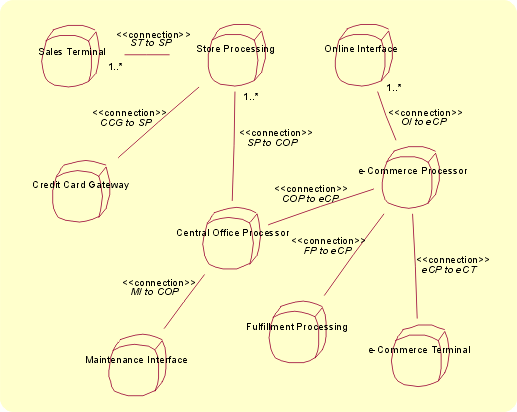
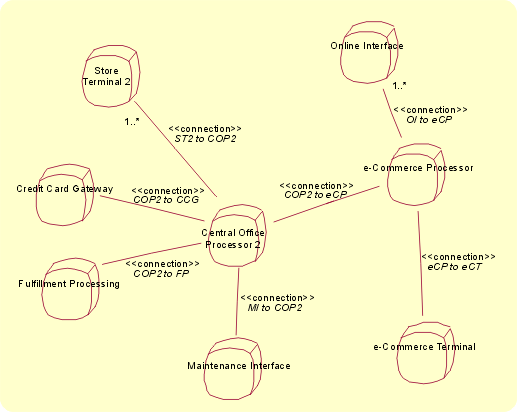
As you move to the design model, localities can be refined to one or more nodes, or more than one locality can be mapped to a single node. And, through the freedom given by the UML definition, localities can represent quite disparate things, ultimately realized, for example, as a collection of hardware platforms, part of a computational resource, or groups of collaborating human resources. Locality diagramsThe figures show Locality diagrams that document different engineering approaches to a click-and-mortar enterprise. The enterprise has a number of retail stores, central warehouses, and a web presence. In the first solution, there is processing capability in the stores. In the second solution, all the terminals are connected directly to a central office processor. In each case, characteristics can be set for the localities that are required to realize the design. These days, most people would agree that the first example is a better design. However, the solution in the second example might become superior in a few years.
Locality Diagram, Example 1.
Locality Diagram, Example 2. |
© Copyright IBM Corp. 1987, 2006. All Rights Reserved. |

