| Guideline: Describing the Run-Time Architecture for J2EE Applications |
 |
|
| Related Elements |
|---|
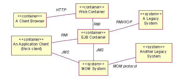
IntroductionThe run-time architecture of an application is described in the Process View, an architectural view that describes the concurrent elements of a system. These guidelines provide specific guidance on how to model the Process View for a J2EE Application. Also see Concept: Process View. Modeling the Process ViewJ2EE components (see Concept: J2EE Overview: J2EE Components) are deployed to environments called Containers. See Concept: J2EE Overview: J2EE Containers for a description of each of the kinds of containers defined by J2EE. Each container is a concurrent element, and so should appear in the Process View of the architecture. Other important concurrent elements that typically appear in the high-level process view are external systems. The following is a typical diagram of the high level process view for a J2EE Application.
In a real example, we would see a specific vendor's Message Oriented Middleware (MOM) represented, as well as specific legacy systems and application clients. However, Web Container and EJB container are standard containers that should appear in all J2EE process views. Note that this diagram does not show the physical distribution of these systems over specific hardware nodes. That is shown in the Deployment Model (see Guideline: Describing Distribution for J2EE Applications). In this example, we see the selected inter-process communication mechanisms employed between the containers. J2EE provides specific inter-process communication mechanisms. These are:
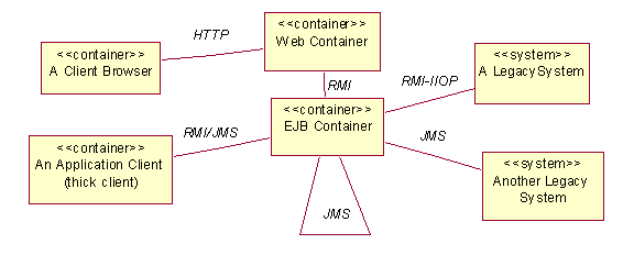
In defining the process view, one important decision is when to use JMS vs. RMI or RMI-IIOP. In this example, the Application Client, EJB Container, and Another Legacy System use messaging to communicate. However, it is not clear which elements communicate with which. To resolve the ambiguity, consider dropping the MOM System from the diagram, and showing JMS as the association between elements that communicate by messaging. Another ambiguity is whether EJBs communicate amongst themselves via messaging. This can be clarified by showing a JMS association from the EJB container to itself. The final diagram then becomes:
The process view, however, is more than just containers and high level systems. It also addresses concurrency within these containers and systems. The process view should identify and model the following kinds of active classes.
When using JMS, you can choose to relate message producers and consumers directly, or model the relationship more precisely by modeling topics and queues.
Interaction diagrams are used to show both synchronous and asynchronous communication between design elements. They can
also be used to analyze concurrent behavior for performance and logic problems. In particular, the software architect
can look for frequent messaging or high volumes of data transfer across the network. This may cause the architect to
redesign interfaces, or reassign design elements between threads of control, between servers, or between client and
server. Note that within an EJB container, threads and processes are managed by the EJB container - EJBs cannot create or manage threads. Logically every EJB should be considered an active class, however, since calls to session beans and entity beans are synchronous blocking calls, these are generally not modeled as active classes. The process view for an EJB container is generally limited to the one concurrency mechanism available - JMS with JMS message-driven beans. Even though session beans and entity beans are not generally modeled as active classes, there are concurrency issues - such as one EJB reading the database while another writes. These issues are handled using transactions. The approach to using transactions should be documented in the project-specific guidelines. Allocating Design Elements to Active ClassesTask: Describe the Run-time Architecture talks about the need to allocated design elements to processes and threads. In a J2EE application, all web components are allocated to the web container, and all EJBs to the EJB container. Because of this simple relationship, there is no need to model this allocation. If, however, your design includes additional concurrent processes (such as two different application clients) it may be useful to specify which design elements execute on each application. For Java threads, message-driven beans, and JMS topics and queues, the issues are more to do with how these inter-communicate, in order to avoid deadlock, inconsistent data, and so forth. This is best explored by examining use-case realizations that include these elements. Other Modeling AlternativesBecause of the affinity between the Process View and Deployment View, the high level diagrams for these views are often combined. Also, because each J2EE container is not only a process, but is also an execution environment, it may be modeled as a "logical node" instead of as an active class. |
© Copyright IBM Corp. 1987, 2006. All Rights Reserved. |

